Professional field project • July 31-August 6, 2018

Gaston Gamma 850 PIM Fault Isolation

Over three visits, I found and corrected crossed B-band transmit lines, then worked from the ground with the tower climbing crew to trace the remaining PIM problem. After the climbers brought down the G1 antenna, I tested it on the ground and confirmed that both ports failed.

Root cause isolated; replacement antenna pending
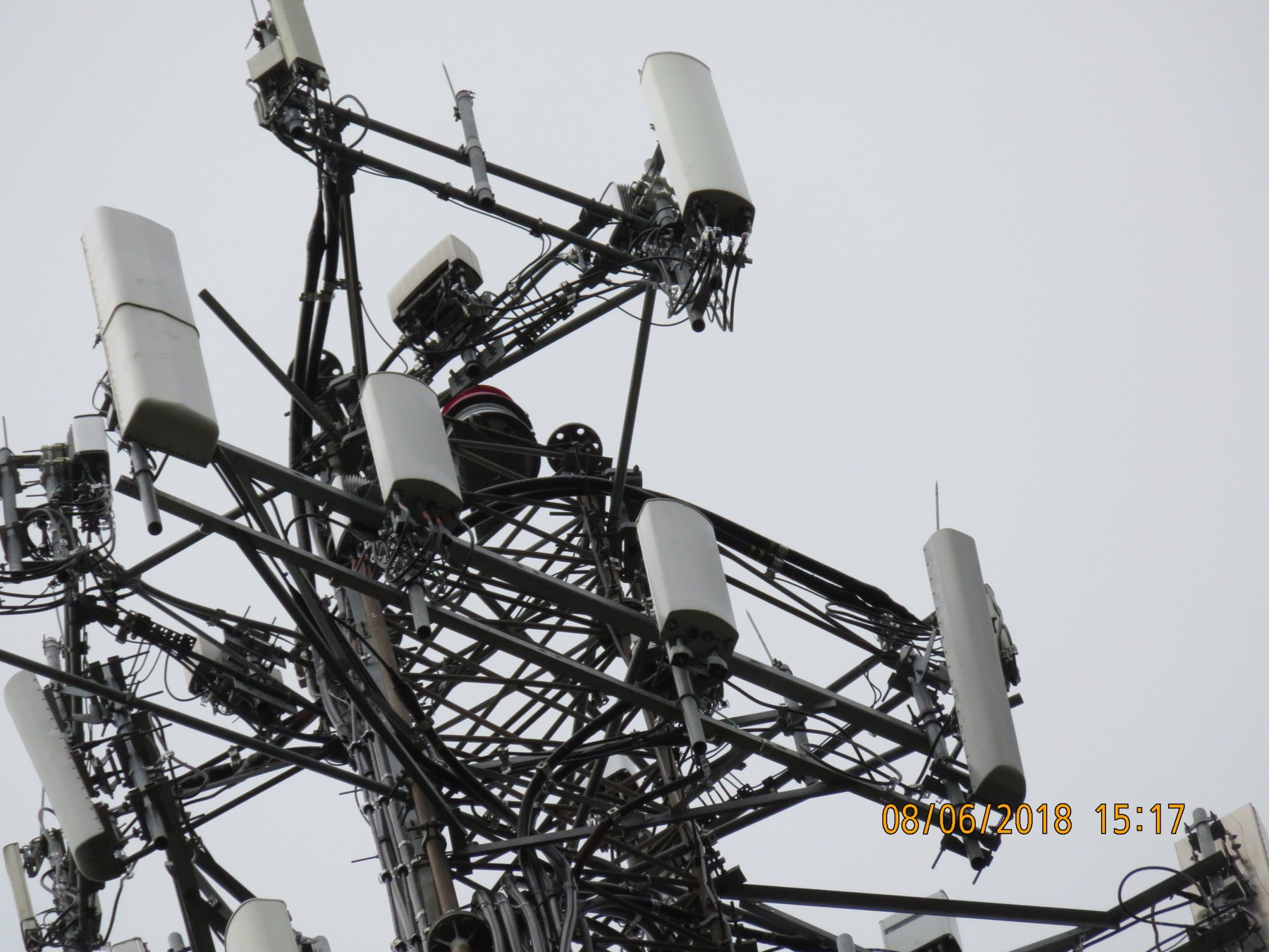
Dense Gaston tower head where the Gamma 850 antenna fault was investigated
Gaston tower head during the August 6 maintenance visit, when the climbing crew removed the G1 antenna for ground testing.
My role: I worked from the ground alongside the tower climbing crew; I did not perform the tower climbs. I verified feeder routing, corrected the crossed transmit lines and color coding, ran and interpreted the ground-side PIM tests, coordinated the climbers' jumper swaps and known-good load testing with the antenna disconnected, tested the removed antenna on the ground, and assembled the evidence needed for the Amphenol RMA.
3 visitsQuality-ticket and maintenance work from July 31 through August 6
40.0 dBSeparation between the passing load control and failing BG antenna result
24/24 PASSSupporting FiberChek inspections across radio and RBS endpoints
RMA-readyFailure reports, model and serial, and field photos assembled

Start by correcting the signal path

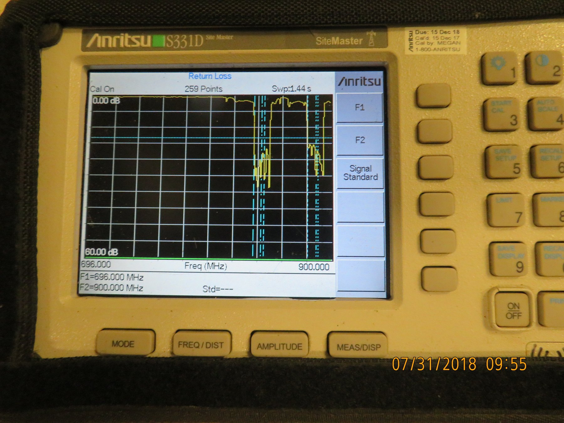
The July 31 quality ticket revealed crossed B-band transmit lines. I traced and verified the 850 LTE RF paths through the site equipment and hardlines, disconnecting and checking branches as needed and using the Anritsu during line identification. I then corrected the crossed connections and color coding.
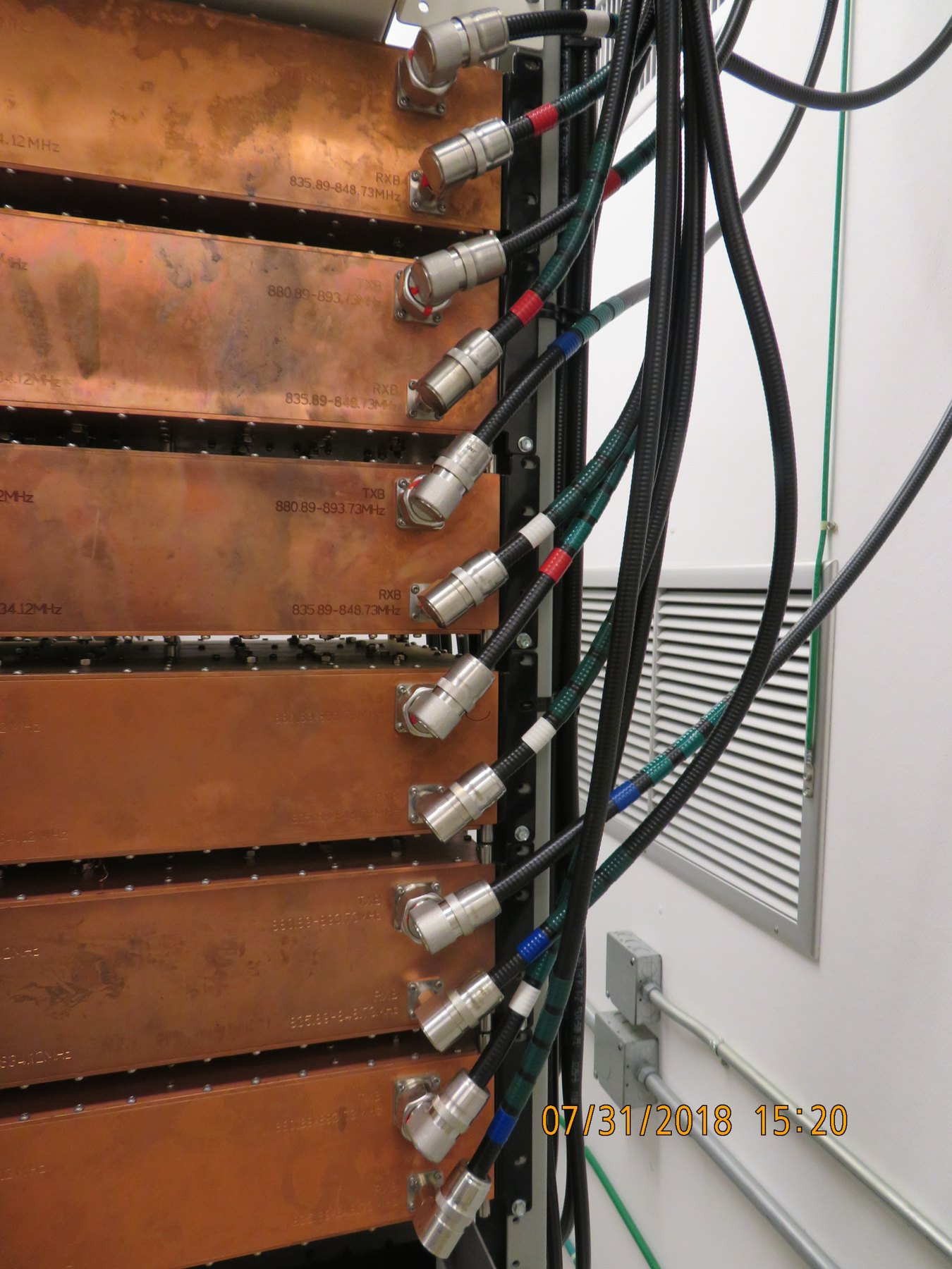
Crossed Gaston B-band transmit lines at the quadplexer bank
The crossed B-band transmit lines before routing and color-code correction.
Anritsu Site Master return-loss trace used during Gaston troubleshooting
Anritsu return-loss measurement used while tracing and verifying RF line routing during the crossed-line investigation.

The isolation sequence

  1. The ground hardline load ruled out the ground equipment. Loading the Gamma 850 branch at the ground hardline showed that the PIM source remained above the ground equipment.
  2. The antenna jumper swap moved the problem. I had the climbing crew swap the BG and BGG coax jumpers at the antenna while I compared the PIM behavior from the ground. The problem moved from branch 3 to branch 4, pointing to the G1 antenna rather than the feeder path.
  3. A known-good PIM load passed when connected in place of the antenna. With the known-good load substituted for the antenna on the BG test path, the control measured -159.8 dBc against a -143.0 dBc threshold.
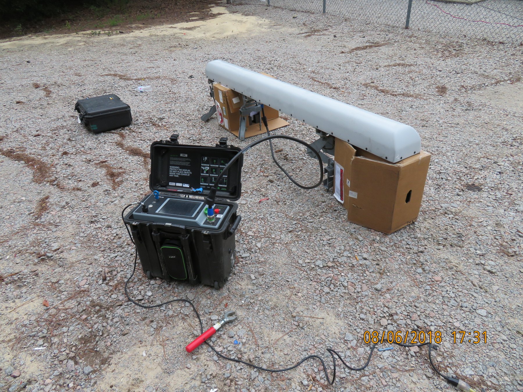
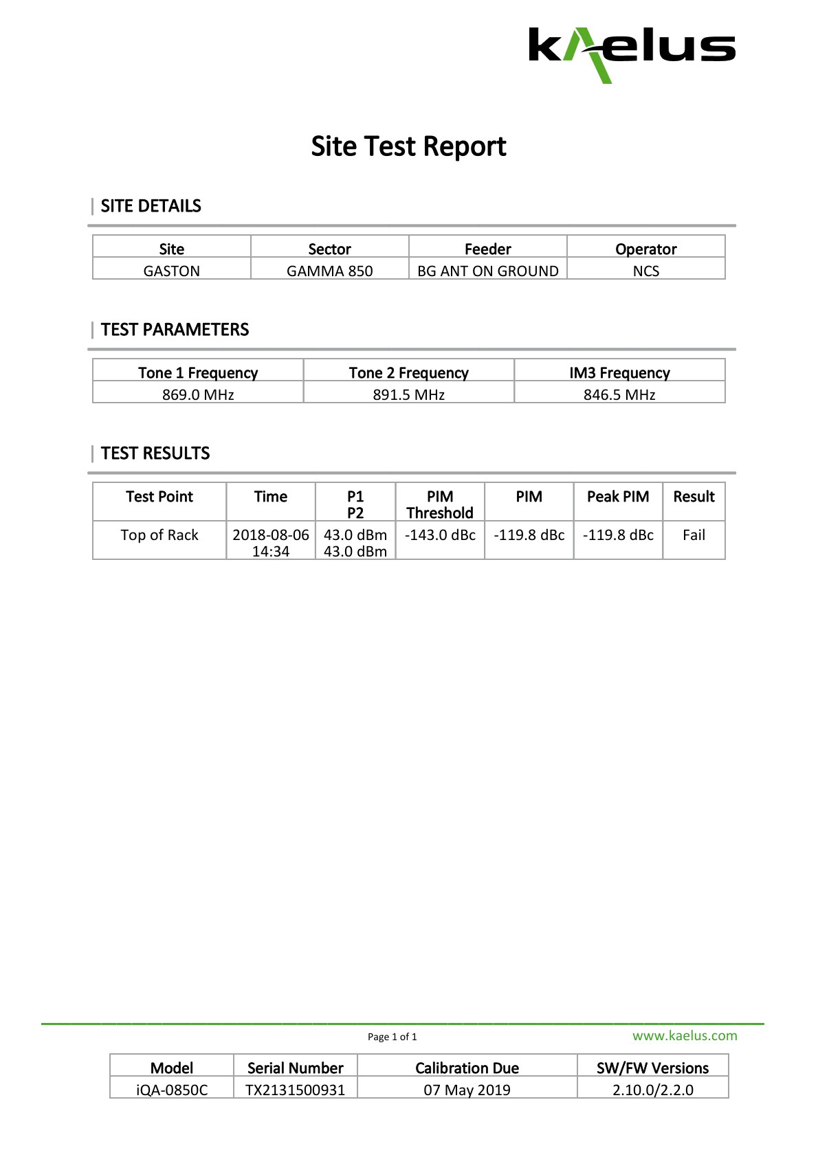
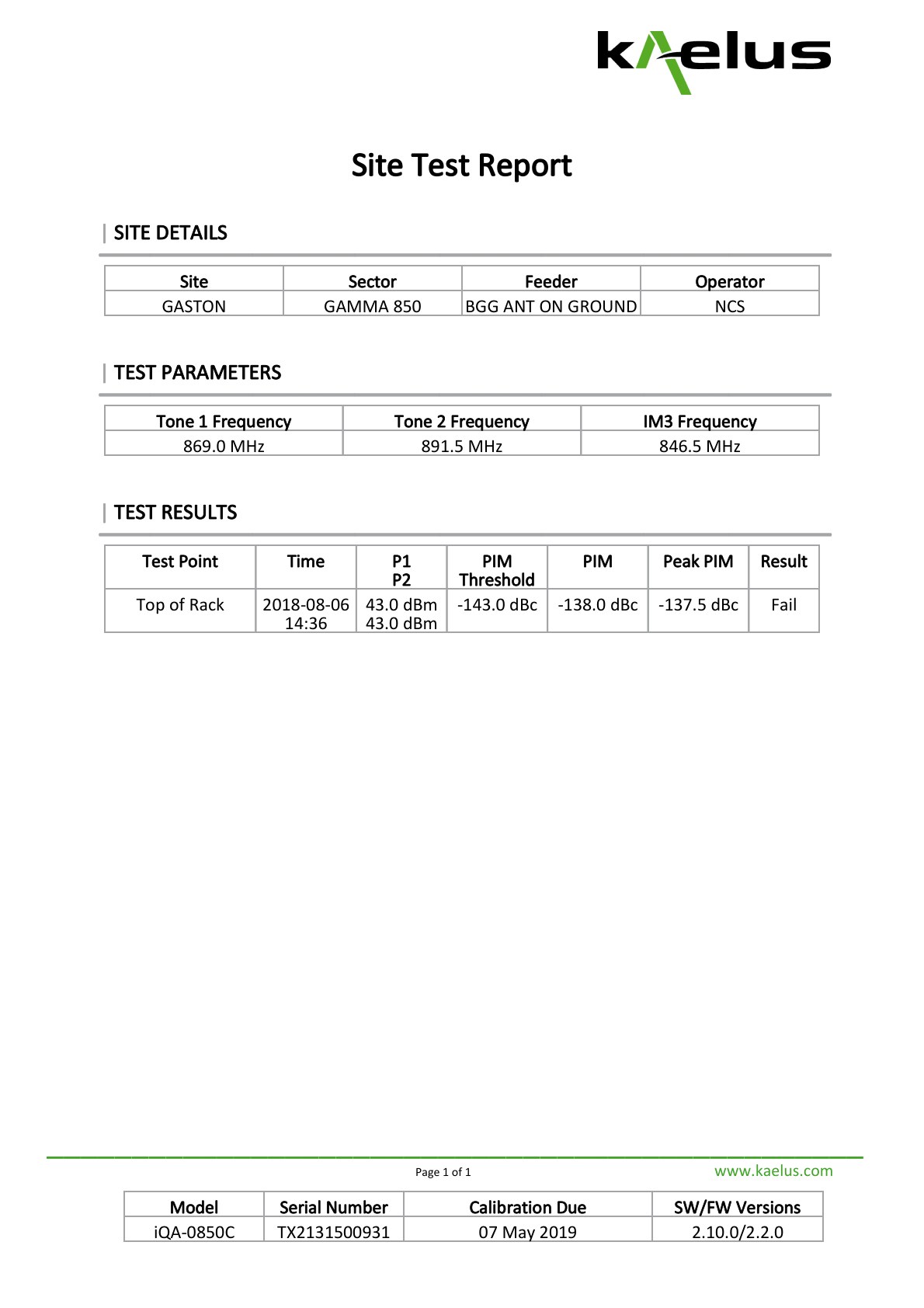
  4. The removed G1 antenna failed on both tested ports. After the antenna was brought down, I tested it on the ground. The two tested antenna ports, identified in the test records as BG and BGG, measured -119.8 dBc and -138.0 dBc respectively, so both failed the -143.0 dBc threshold.
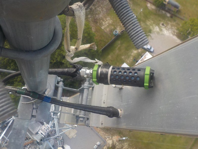
Known-good PIM load connected in place of the Gaston antenna
Known-good PIM load connected in place of the antenna during fault isolation.
Gaston G1 antenna connected to a PIM tester on the ground
The removed G1 antenna connected to the PIM analyzer for ground-level confirmation.

Compare the load and antenna results

Gamma 850 PIM comparison · threshold -143.0 dBc
Test pointPIMPeak PIMResult
BG known-good load replacing antenna-159.8 dBc-159.7 dBcPASS
BG antenna on ground-119.8 dBc-119.8 dBcFAIL
BGG antenna on ground-138.0 dBc-137.5 dBcFAIL
Passing Gaston BG PIM known-good-load control report at negative 159.8 dBc
Control: the load passed at -159.8 dBc.
Failing Gaston BG antenna-on-ground PIM report at negative 119.8 dBc
Fault: the BG antenna port failed at -119.8 dBc—a 40.0 dB separation from the known-good load control.
Failing Gaston BGG antenna-on-ground PIM report at negative 138 dBc
The second G1 antenna port also failed, at -138.0 dBc.

Supporting fiber baseline

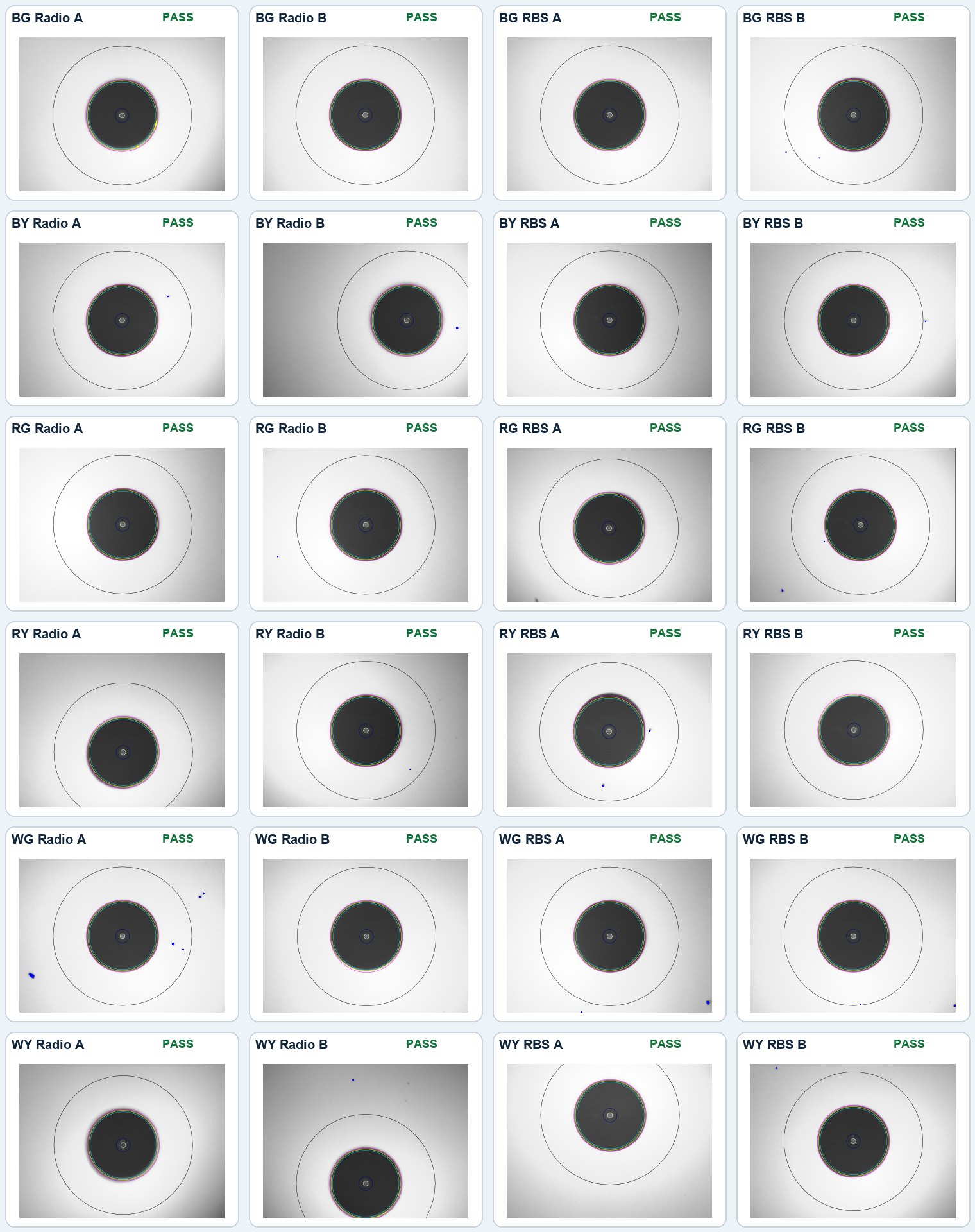
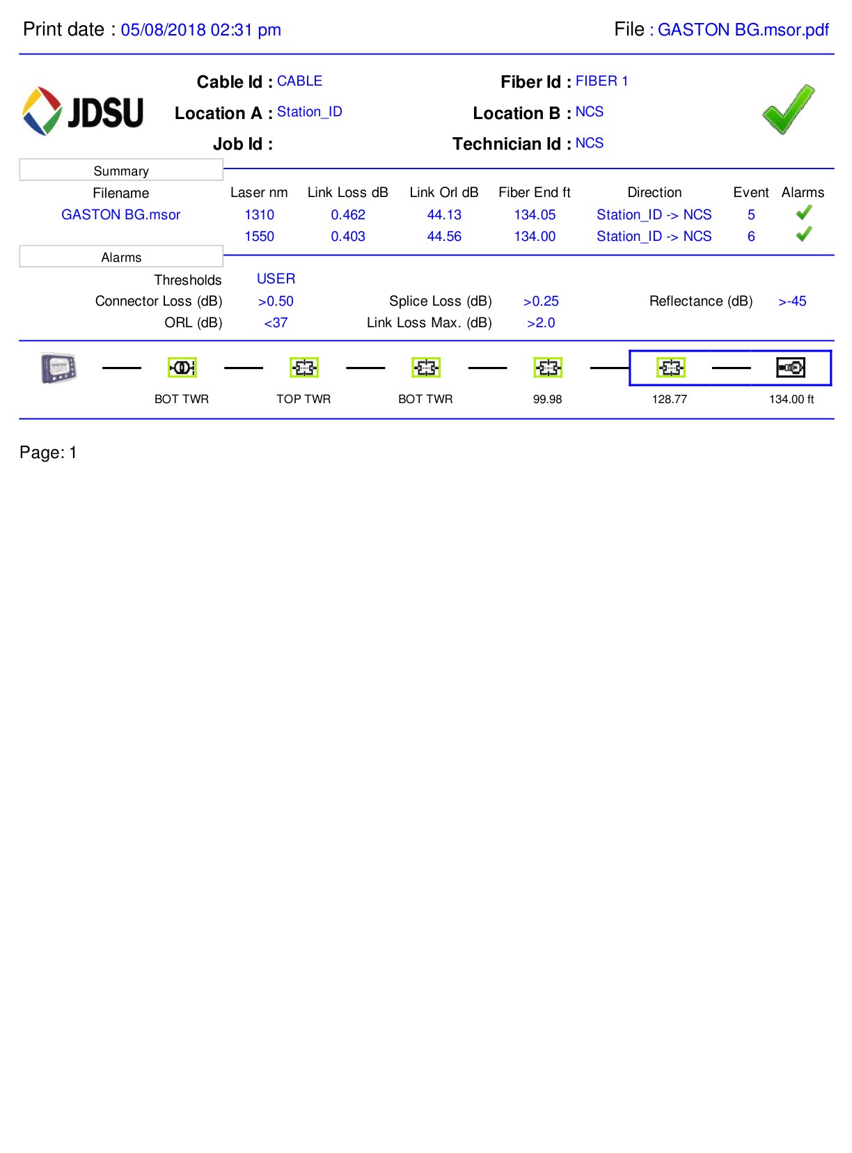
Earlier site records provided a clean fiber baseline: all 24 FiberChek inspections passed across six color pairs and their radio and RBS endpoints, and all six OTDR paths passed at both 1310 nm and 1550 nm. A teammate completed these tests, so they are included only as supporting site information and are not presented as my work.

Supporting dual-wavelength OTDR results
Path1310 nm loss1550 nm lossResult
BG0.462 dB0.403 dBPASS
BY0.398 dB0.376 dBPASS
RG0.431 dB0.323 dBPASS
RY0.412 dB0.273 dBPASS
WG0.359 dB0.247 dBPASS
WY0.464 dB0.342 dBPASS
Matrix of 24 passing Gaston FiberChek inspection images
All 24 supporting FiberChek inspection results, organized by color pair and Radio or RBS endpoint.
Passing Gaston BG dual-wavelength OTDR summary
Representative BG OTDR summary: 0.462 dB at 1310 nm and 0.403 dB at 1550 nm, both passing.

Prepare the antenna RMA

I documented the antenna model and serial alongside the PIM reports, crossed-line photos, and isolation sequence. That package supported the request for a replacement antenna from Amphenol.
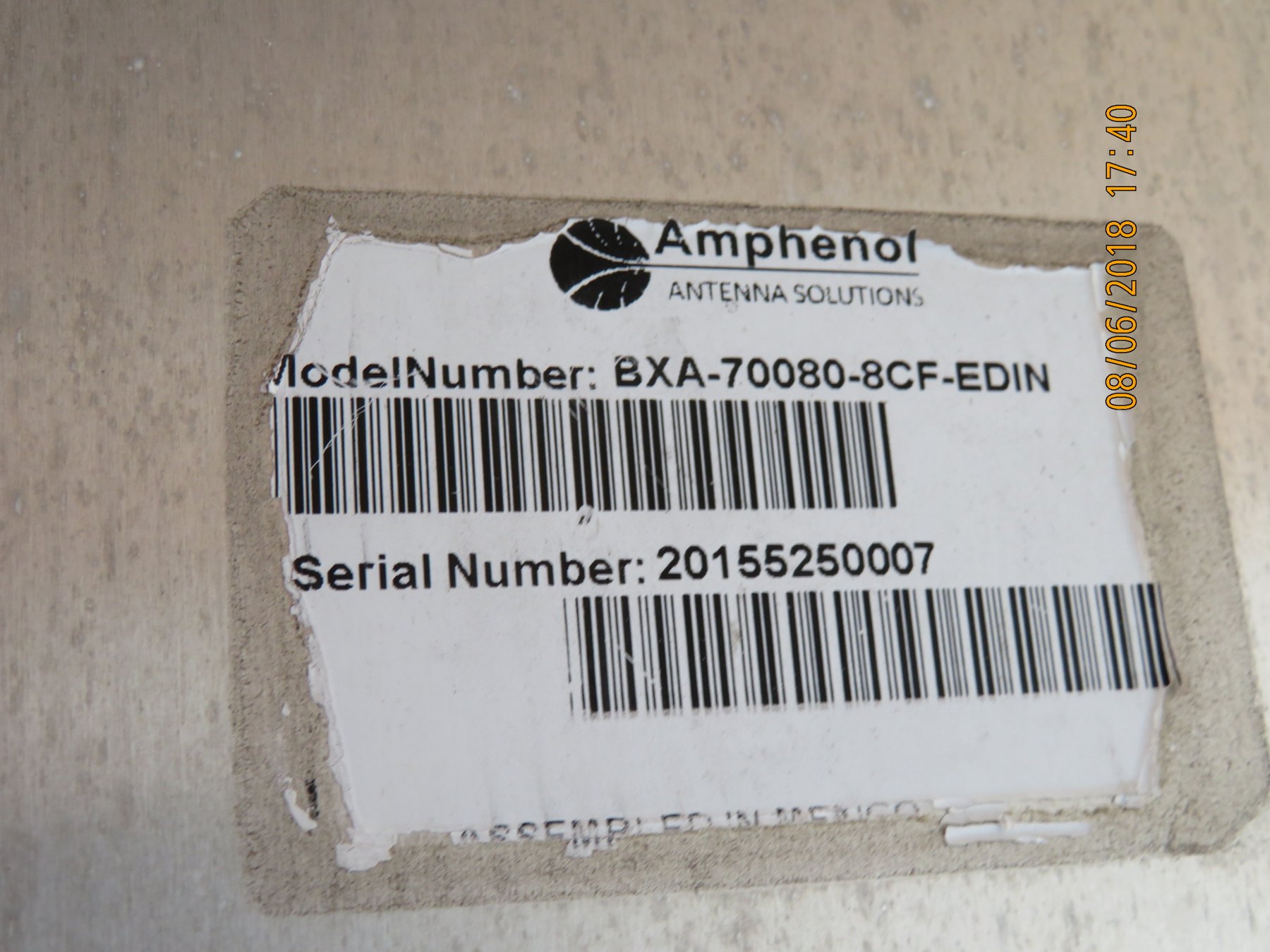
Amphenol model and serial label on the failed Gaston G1 antenna
Model and serial documentation supplied with the PIM reports for the replacement request.
Remaining work: The August 6 update recorded the maintenance ticket at 50% while the replacement G1 antenna was still being supplied. I completed the investigation and RMA evidence, but the final antenna replacement had not been completed.